Der Phaser
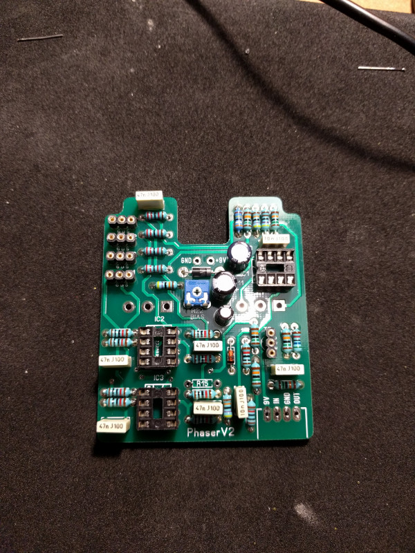
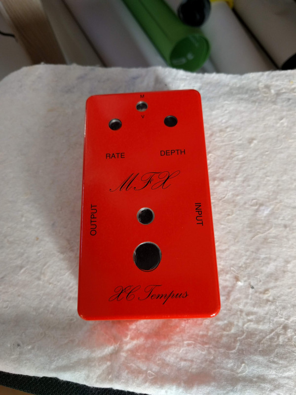
Das Musikding MXR Phase 90 kit with additional Depth control. I'll be putting this into a Tayda Burnt Orange powder coated 125B enclosure. These enclosures are only $6 and even though the one I received isn't impeccable it looks great for such a cheap powder coated enclosure.
Bill of materials
Musikding published a bill of materials but unfortunately it doesn't contain the numbering of the components. Below a table with the complete numbering.
| Part number | Value |
|---|---|
| R1, R3, R4, R6, R7, R9, R10, R12, R13, R21 | 10k |
| R2, R25, R28 | 470K |
| R5, R8, R11, R14, R15* | 22k |
| R16, R17, R18, R20, R23, R26 | 150k |
| R19 | 56k |
| R22 | 250k trim pot |
| R24 | 4,7k |
| R27 | 3,9M |
| Rled | 2,2k |
| C1, C9 | 10n |
| C2, C3, C4, C5, C6, C7 | 47n |
| C8 | 10μ |
| C10 | 15μ |
| C11 | 100μ |
| D1 | Zener 5V1 0,5W |
| D2 | 1N4001 |
| Led | Red |
| T1, T2, T3, T4 | 2N5952 |
| T5 | 2N4125 |
| IC1, IC2, IC3 | TL072 |
| P1, P2 | C500K (Reverse Log) |
* R15 is optional (“R28 mod”) or could be switched on (modern) or off (vintage) with a SPDT switch
R28 Mod
I'm planning to incorporate the R28 mod in this build with a SPST switch for switching between vintage (“Script”) mode and modern mode.
stinkfoot.se - Modifying the MXR Phase 90 (M-101)
DIY Guitar pedal projects - Phase 90 mods
Graphics
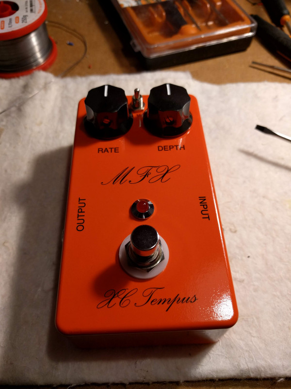
Opted for the classic Script design and modified it slightly while trying to stay close to the original. Dubbed the effect “XC Tempus”. Used waterslide decal to transfer the design. Finished it off with Motip acrylic clear varnish.
Interior
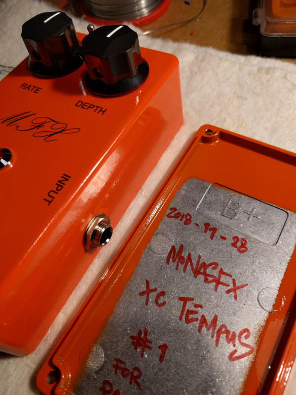
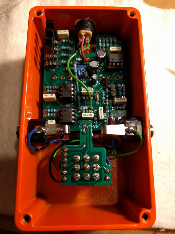
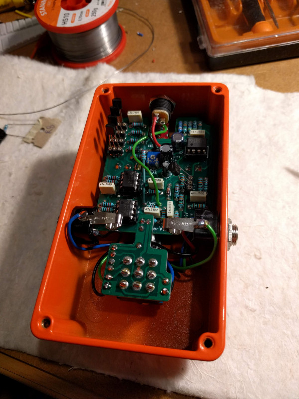
When boxing the effect I ran into some small issues that don't affect the functionality or the outside looks of the effect but these small imperfections do trigger my OCD.
- The jack connectors are positioned a wee bit too high so the main PCB doesn't fit nicely. I would have also preferred if I could have turned the connectors 90°.
- I've soldered the 3PDT on the wrong side of its PCB so the wiring for the jack connectors is also reversed. I ordered a new Der Phaser kit and the 3PDT PCB that is included now even has those instructions printed on the PCB itself. This was a huge relief for me, apparently I was not the only one to solder the switch the wrong way around.
- The DC connector should be positioned a bit more closer to the bottom, it was a really tight fit now with the SPST switch.
Other things that could be improved:
- IC sockets. From now on I'm only going to use precision sockets. The sockets I used for this project have pins that could go loose as opposed to precision sockets, those pins are more stable.
- Wire the SPST switch from the back of the PCB.
- Better test the effect before boxing it. I now had to solder some pads I forgot after I had already boxed the effect.
